Apalis Smart Vision Baseboard
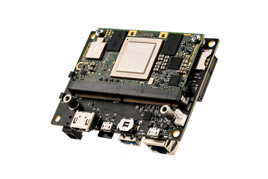
This repository contains open hardware design files for Antmicro’s Apalis Smart Vision Baseboard - a custom baseboard for the Toradex Apalis family of SoMs (Systems on Module). The board has a unified FFC connector exposing the MIPI CSI-2 interfaces of the Apalis modules. The FFC connector is electrically compatible with a range of image acquisition platforms developed by Antmicro.

Languages
Apalis Smart Vision Baseboard
Copyright (c) 2016-2021 Antmicro
Overview
This repository contains open hardware design files for Antmicro’s Apalis Smart Vision Baseboard - a custom baseboard for the Toradex Apalis family of SoMs (Systems on Module). The board has a unified FFC connector exposing the MIPI CSI-2 interfaces of the Apalis modules. The FFC connector is electrically compatible with a range of image acquisition platforms developed by Antmicro.
Repository structure
The main repository directory contains the Altium PCB project file, the Outjob file, LICENSE and README. The remaining files are stored in the following directories:
PCB- contains all Altium design filesLibraries- contains the component librariesDocumentation- contains selected files for device fabrication (schematics in PDF, BoM) generated from the Altium project filesImages- contains graphics for this README3DModel- contains files defining the mechanical model of the assembled board
Key features
- Toradex Apalis SoM edge connector
- FFC interface exposing up to 2 x 4-lane MIPI CSI-2, depending on the Apalis SoM used
- mSATA connector
- miniPCIe connector
- USB 3.0 host interface
- HDMI output interface
- 2 x Micro USB (debug and OTG)
- Gigabit Ethernet RJ45 connector
- Micro SIM slot
- RTC battery backup
- 9-24V DC power supply voltage
The PCB project files were prepared in Altium Designer 14.1.
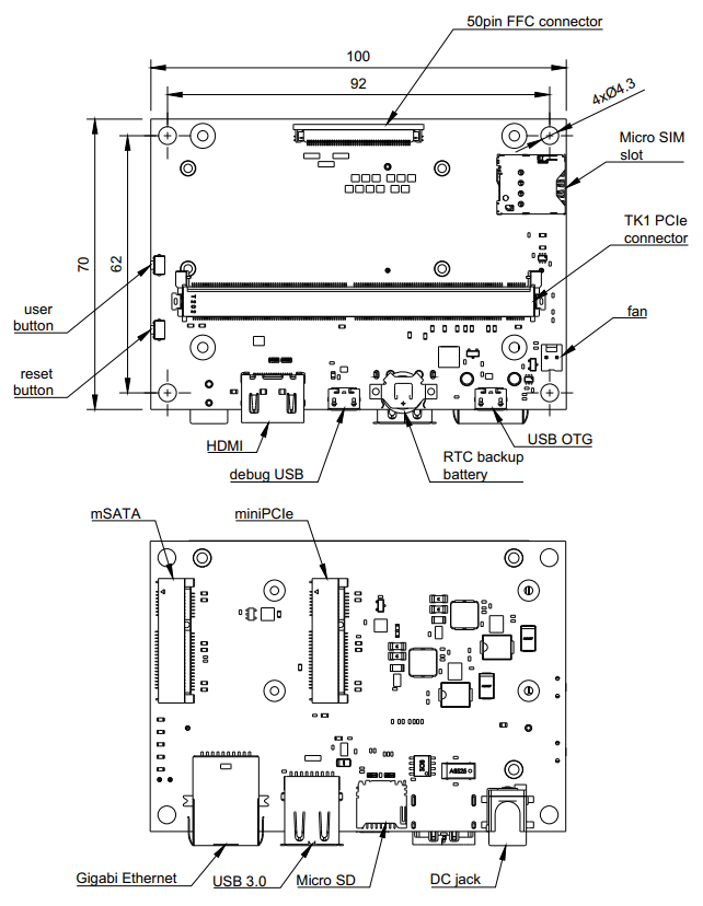
Board layout & dimensions
The picture below presents a general layout of the PCB with marked I/O interfaces.
Getting started
The board can be produced and assembled using the provided design files. Refer to the mechanical layers for more information regarding the PCB stackup recommended for fabrication. The board accepts power supply voltage in the 6-24VDC range. It is recommended to use a 12V 2A DC supply to power the board. The module will start automatically right after applying a power supply.
Debug UART connection
Most of the debug messages are provided through the serial console. The
board is equipped with an FTDI chip providing the UART interface to the
host PC. Refer to the schematic sheets for more details. The default
debug UART channel is accessible through /dev/ttyUSB0 (assuming that
there are no other FTDI units connected to your PC). The default
baudrate for the serial debug connection is 115200 baud with an 8-bit
transmission, 1 stop bit and with no flow control.
License
Relevant projects
Nothing found
Apologies, but no results were found.