Antmicro UltraScale+ Processing Module
Antmicro’s Ultrascale+ Processing Module is a specialized development board supporting Enclustra Mercury+ XU1 module with an embedded Xilinx Zynq UltraScale+ FPGA MPSoC, created for high-speed data processing applications. The UltraScale+ Processing Module is an excellent starting point for developing your next generation FPGA MPSoC product in machine vision, image acquisition & processing, industrial motion control and other applications.

Languages
Antmicro UltraScale+ Processing Module
Copyright (c) 2016-2023 Antmicro
Overview
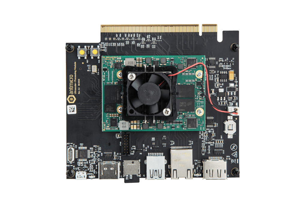
Antmicro’s Ultrascale+ Processing Module is a specialized development board supporting Enclustra Mercury+ XU1 module with an embedded Xilinx Zynq UltraScale+ FPGA MPSoC, created for high-speed data processing applications. The UltraScale+ Processing Module is an excellent starting point for developing your next generation FPGA MPSoC product in machine vision, image acquisition & processing, industrial motion control and other applications.
Project structure
The main directory contains the Altium PCB project file, the Outjob file, LICENSE and README. The remaining files are stored in the following directories:
PCB- contains all Altium design filesLibraries- contains the component librariesDocumentation- contains selected files for device fabrication (schematic in PDF, BoM) generated from the Altium projectimg- contains graphics for this README3DModels- contains files defining the mechanical model of the assembled board
The PCB project files were prepared in Altium Designer 14.1.
Key Features
- Enclustra Mercury+ module connector
- 28 differential pairs available on the edge backplane connector
- 48 differential pairs available on the board-to-board Samtec QSE expansion connector
- DisplayPort as the default video output from the system
- FPGA-driven HDMI output display interface
- MicroSD card slot
- USB 3.0 host interface
- Gigabit Ethernet
- DisplayPort output video interface
- 14-pin JTAG interface
Please note that the backplane connector available on board is not pin-compatible with PCIe x16 standard.
Getting started
The board can be produced and assembled using the provided design files. Please take a look at the mechanical layers for more information regarding the PCB stackup recommended for fabrication. The board should be powered by a 12V DC power supply. It is recommended to use the USB debug console interface of the UltraScale+ Processing Module for the first boot. Use a micro-USB cable to connect the board to your PC. The board has a built-in dual channel USB/UART converter which is USB bus powered. Two new serial devices should appear in your system. One of them, designated with the lower number (/dev/ttyUSB0) is used as a debug console whereas the other (/dev/ttyUSB1) is a general purpose UART connected to the FPGA fabric. Use your favourite terminal client (e.g. minicom) to open the debug console interface port. The default connection baudrate is 115200 with 8-bit transmission, 1 stop bit and no flow control.
License
This project is published under the Apache-2.0.
Relevant projects
Nothing found
Apologies, but no results were found.