Video Booster Board
This repository contains a KiCad PCB project for an open hardware board design that allows to improve the quality of HDMI video signals transmitted over long cables.

Languages
Video Booster Board
Copyright (c) 2019-2021 Antmicro

Overview:
This repository contains a KiCad PCB project for an open hardware board design that allows to improve the quality of HDMI video signals transmitted over long cables.
Key features:
- HDMI signal preconditioning with a pair of PTN3363 HDMI level shifters.
- Signal equalization controlled with on-board DIP-Switch
- On-board SiLabs EFM32HG322F64 MCU for interactive control and board monitoring
- Supports different EDID connection scenarios
Mechanical layout and dimensions
The board has been mechanically optimised for usage with the Numato Opsis open video capture device. It is possible to use it with different platforms using HDMI extender cables.

It follows the data flow diagram presented below:

Getting Started
Please refer to KiCad schematic files for more information regarding
hardware functionalities implemented in the design. The PCB layout has
been defined with a 4-layer stackup. Please check the geometry of
differential traces implemented in the design with stackup offered by
PCB vendor for optimal impedance match of HDMI traces. There is a BOM
document generated from the schematics and shared in this repository.
Please short the J5,J7,J8,J12 solder jumpers on the bottom side of the
PCB. This will relay the EDID signals on both HDMI channels from input
to output. Short the J11,J4 jumpers if you plan to experiment with the
provided example MCU firmware. This will make the on-board MCU
accessible on EDID bus driven from J2 HDMI input connector. Please
check the schematics and software codebase for any other jumper
configuration.
Example firmware
The EFM32 MCU used in the design comes with a factory programmed
AN0042 bootloader. In order to make the MCU compatible with the
provided example firmware it is advisable to replace the default
bootloader with Toboot over SWD
interface using OpenOCD. The SWD signals from the
MCU are exposed on test pads marked with IO and CLK on the bottom
side of the Video Booster Board. Additionally there are test pads with
system ground and power supply exposed next to them.
To upload the Toboot bootloader, please follow this
instruction. Be
aware that the provided flashing instruction was originally created for
a different hardware platform so the SWD connection wiring differs a
little.
There is an example-firmware folder included in this repository, which
contains a sample firmware driven by the RTOS derived from the Zephyr
project. The firmware makes the
on-board EFM32 MCU act as an EDID slave for the transmitting device.
In order to build the example firmware please use the following commands:
git clone https://github.com/antmicro/video-signal-booster-board
cd video-signal-booster-board
git submodule update --init --recursive
cd example-firmware
python3 -m pip install -r zephyr/scripts/requirements.txt
wget https://github.com/zephyrproject-rtos/sdk-ng/releases/download/v0.10.3/zephyr-sdk-0.10.3-setup.run
chmod +x zephyr-sdk-0.10.3-setup.run
./zephyr-sdk-0.10.3-setup.run -- -d <zephyr_installation_path>
export ZEPHYR_TOOLCHAIN_VARIANT=zephyr
export ZEPHYR_SDK_INSTALL_DIR=<zephyr_installation_path>
source zephyr/zephyr-env.sh
west init -l zephyr
west update
make
Once the firmware is compiled, connect the micro USB cable to the Video Booster Board and upload the firmware using the following command:
dfu-util -d 1209:70b1 -D build/zephyr/zephyr.bin
Please note that in this setup the firmware doesn't stick permanently. After a power cycle a bootloader will start again. This simplifies the developing process.
The example firmware makes the MCU on Video Booster Board accessible on
I2C/EDID bus slave device under the address of 0x3a (7-bit notation).
It's possible to test the I2C/EDID communication by connecting an I2C
master device to TX source HDMI connector (J2). The example firmware
makes MCU offer a single 8-bit configuration register. Two least
significant bits of this register control the states of the TX_EQ0 and
TX_EQ1 signals that define the equalization settings of U3 HDMI
level shifter. The states of those signals are also displayed on D8
D9 LEDs installed on board.
A sample Python code that would drive the MCU over I2C bus is:
python
import smbus
bus = smbus.SMBus(<i2c_bus_number>)
bus.write_byte_data(0x3a, 0x00, 0x03)
3D-printable enclosure

There are also 3D-printable enclosure .stl files available in the
3d-models directory. The enclosure allows the electronics to be
covered and attaches the Video Booster Board to the Numato board
installed in a typical thin mini-ITX chassis. A connector is the source,
B is the sink of the RX/TX signal.
For printing the enclosure, use slicer settings matching your used 3D printer and filament. Setting layer thickness to a value between 0.15mm and 0.2mm is sufficient. The image below shows proposed print orientation.
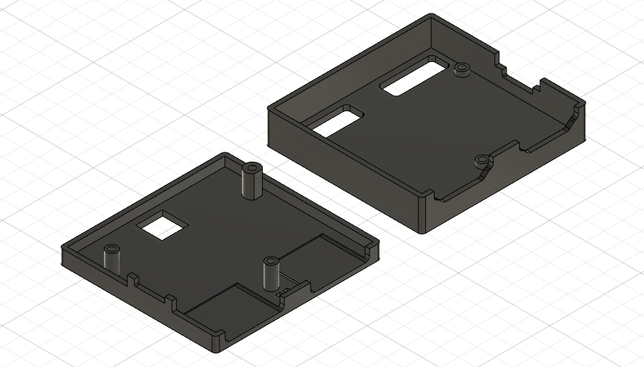
Enclosure can be assembled with the board using 3 M1.6x8 flathead bolts.
License
Relevant projects
Nothing found
Apologies, but no results were found.